What are the structures of check valves?
What is a lift check valve?
As shown in Figure 1-1,

Figure 1-1 Type straight-through lift check valve
The valve disc moves up and down along the centerline of the valve seat. Its valve body is exactly the same as the globe valve body and can be used universally. A pressure relief hole is machined in the lower part of the valve disc guide sleeve or the upper part of the valve cover guide sleeve. When the valve disc rises, the medium in the sleeve is discharged through the pressure relief hole to reduce the resistance when the valve disc opens. This valve has large fluid resistance and can only be installed on horizontal pipelines. If an auxiliary spring is installed in the middle of the valve disc, and the valve disc is closed under the action of the spring force, it can be installed in any position, see Figure 1-2.

Figure 1-2 H42 vertical check valve
Lift-type bottom valve, as shown in Figure 1-3, is a special check valve. It is mainly installed at the end of the water pump suction pipe that cannot self-prime or does not have a vacuum pump to pump air and water. The bottom valve must be submerged in the water. Its function is to prevent the water entering the suction pipe or the water that has been poured into the water pump and the suction pipe before starting from flowing back to ensure the normal start of the water pump.

Figure 1-3 Lift-down bottom valve
The lift bottom valve is mainly composed of valve body, valve disc and filter screen. The function of the filter is to prevent debris in the water source from entering the suction pipe to avoid damage to the water pump and related equipment. The valve shown in Figure 1-4 is specially designed for systems with very rapid backflow of media. This valve uses a deceleration damping device that acts during the final stages of closing. In addition, this kind of valve also uses a certain shape of the closing member, so the impact pressure of this kind of check valve is very small.

Figure 1-4 H41 type DC slow-closing silencer check valve
Lift check valves have the shortest lift compared to other types of check valves, so lift check valves may be quick-closing valves. However, if dirt gets into the movement guide mechanism of the closure, the closure may get stuck or close slowly. Additionally, if used in a viscous manner, the movement of the closure in its guide may be slowed down. An exception is the spherical disc lift check valve shown in Figure 1-5. This valve has a large gap between the spherical disc and its guide mechanism, making it durable in applications where dirt is present.

Figure 1-5 H40 vertical check valve
What is a swing check valve?
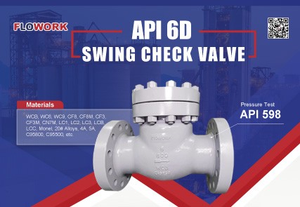
As shown in Figure 1-6, the valve disc is disc-shaped, and the valve disc rotates around a fixed axis outside the valve seat channel. The swing check valve is composed of a valve body, a valve cover, a valve disc and a rocker; the valve channel is streamlined and has low fluid resistance. High temperature and high pressure check valves can adopt a centerless flange pressure sealing structure. The sealing ring is made of formed flexible graphite packing or stainless steel. The sealing ring is pressed by the medium pressure to achieve sealing. The higher the medium pressure, the better the sealing performance.

Figure 1-6 Swing check valve
As the size of a swing check valve increases, the disc weight and stroke eventually become too large for normal operation of the valve. For this reason, swing check valves larger than DN600 (NPS24) are designed as multi-disc swing check valves. This type of valve has a multi-valve seat partition on the medium channel, on which some conventional Swing valve disc (Figure 1-7).

Figure 1-7 Swing multi-disc horizontal check valve
To prevent the disc from being in the stall position, swing check valves can also be installed vertically. However, in the fully open position, the closing torque determined by the weight of the valve disc is very small, so this type of valve will tend to close slowly. To overcome this sluggish response to reverse flow, the valve disc can be equipped with a weighted or spring-loaded lever (Figure 1-8).

Figure 1-8 H44 slow-closing check valve
The check valve shown in Figure 1-9 is a double-disc swing check valve with a D-shaped disc with torsion spring load, which is placed on a rib across the valve through hole. This structure reduces the distance the center of gravity of the valve disc moves; compared with a single-disc swing check valve of the same size, this structure also reduces the weight of the valve disc by 50%. Due to the torsion spring loading, this valve responds very quickly to reverse flow.

Figure 1-9 H76 double-disc wafer check valve
What is butterfly check valve?
(Figure 1-10) Its shape is similar to that of a butterfly valve. The valve seat is tilted, and the rotating shaft of the butterfly plate (valve disc) is installed horizontally and is located above the center line of the channel in the valve, so that the area of the butterfly plate at the lower part of the rotating shaft is larger than the upper part. When the medium stops flowing or reverses the flow, the butterfly plate relies on its own weight. It rotates to the valve seat due to the action of the counter-current medium. This kind of check valve has a simple structure but poor sealing performance and can only be installed on horizontal pipelines.
Butterfly check valves have the disadvantage of high cost and are more difficult to repair than swing check valves. Therefore, butterfly check valves are usually limited to situations where swing check valves cannot meet the requirements.

Figure 1-10 H47 butterfly check valve
What is a diaphragm check valve?
(Figure 1-11 and Figure 1-12) The closing part is composed of a diaphragm, which deviates from or fits the valve seat.
The check valve shown in Figure 1-11 has a tapered perforated basket-shaped member that serves as a support for the matching diaphragm. This type of valve is installed between two flanges on the pipeline or clamped between pipe joints. Fluid media passing through the cone lifts the diaphragm from its seat, allowing the media to pass through. As soon as the downstream flow ceases, the diaphragm resumes its original shape and closes extremely quickly. One use case worth mentioning is the purge gas line feeding into lines handling slurries and colloidal media. In this case the diaphragm shows great operational reliability, whereas its valve would soon be worn if used.

Figure 1-11 Tapered diaphragm check valve
The check valve shown in Figure 1-12 uses a pleated annular rubber diaphragm. When the valve is closed, the pleated edges of the diaphragm fit into the center of the media channel. The downstream medium causes the pleated membrane to open, so that the edge of the diaphragm retracts from the valve seat. Because the diaphragm is elastically tensioned in the open position and the displacement of the diaphragm edge from the fully open to the closed position is very short, this diaphragm check valve closes extremely quickly. This type of diaphragm check valve is suitable for applications where the medium flow changes within a wide range. However, in situations where this valve may be used, the pressure difference is limited to 1MPa and the operating temperature is only up to 70°C.

Figure 1-12 Ring braided diaphragm check valve


