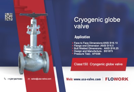
What are the basic parameters of valves?
The basic parameters of the valve are nominal size (DN), nominal pressure (PN), pressure-temperature grade, applicable temperature (℃), applicable medium, flow coefficient (Kv), opening torque (N·m), etc.
What is the nominal size of the valve?
Nominal size is an alphanumeric dimensional designation used for piping system components. It consists of the letters DN followed by a dimensionless integer number that is directly related to a characteristic size such as the bore diameter or outer diameter (expressed in mm) of the end connection. Related.
It should be noted that, unless otherwise specified in the relevant standard, the numbers following the letters DN do not represent measured values and cannot be used for calculation purposes.
The numerical values of nominal dimensions should be consistent with those shown in Table 1-1.
Table 1-1 Nominal size (diameter) series of valves
| DN6 | DN8 | DN10 | DN15 | DN20 | DN25 | DN32 | DN40 | DN50 | DN65 |
| DN80 | DN100 | DN125 | DN150 | DN200 | DN250 | DN300 | DN350 | DN400 | DN450 |
| DN500 | DN600 | DN700 | DN800 | DN900 | DN1000 | DN1100 | DN1200 | DN1400 | DN1500 |
| DN1600 | DN1800 | DN2000 | DN2200 | DN2400 | DN2600 | DN2800 | DN3000 | DN3200 | DN3400 |
| DN3600 | DN3800 | DN4000 |
What is the nominal pressure of the valve?
Nominal pressure is an alphanumeric designation for reference related to the mechanical and dimensional characteristics of a valve, consisting of the letters PN followed by a dimensionless integer number.
It should be noted that unless otherwise specified in the relevant standards, the numbers following the letters PN do not represent measured values and cannot be used for calculation purposes. Nominal pressure has no meaning except in connection with the relevant valve standard. The pressure rating of the valve depends on the PN value, material and design of the valve, and the allowable operating temperature. The pressure rating of the valve is given in the pressure-temperature rating table of the corresponding standard, such as ASMEB16.34 .
The nominal pressure should be as shown in Table 1-2.
Table 1-2 Nominal pressure series of valves
| DINseries | ANSIseries | DIN series | ANSI series |
| PN2.5 | PN20 | PN25 | PN260 |
| PN6 | PN50 | PN40 | PN420 |
| PN10 | PN110 | PN63 | |
| PN16 | PN150 | PN100 |
What are valve pressure and temperature ratings?
When the valve operating temperature exceeds the nominal pressure reference temperature, its maximum operating pressure must be reduced accordingly. The working temperature of the valve and the corresponding maximum working pressure change are referred to as the temperature and pressure gauge, which is the benchmark for valve design and selection (Table 1-3 ~ Table 1-8).
Table 1-3 Pressure-temperature grades of steel valves
| Steel number | base temperature /℃ | Working temperature t/℃ | |||||||||||||
| 10、20、30、WCB | 200 | 250 | 300 | 350 | 400 | 425 | 435 | 445 | 455 | ||||||
| 15CrMo、ZG20CrMo | 200 | 320 | 450 | 490 | 500 | 510 | 515 | 525 | 535 | 545 | |||||
| 12Cr1MoV、15CrMolV、 ZG20CrMoV、 ZG15CrMolV | 200 | 320 | 450 | 510 | 520 | 530 | 540 | 550 | 560 | 570 | |||||
| 1Cr5Mo、ZG1CrMo | 200 | 325 | 390 | 430 | 450 | 470 | 490 | 500 | 510 | 520 | 530 | 540 | 550 | ||
| 1Cr18Ni9Ti、 1Cr18Nil2Mo2Ti、 ZG1Cr18Ni12Mo2Ti | 200 | 300 | 400 | 480 | 520 | 560 | 590 | 610 | 630 | 640 | 660 | 675 | 690 | 700 | |
| Nominal pressure PN/MPa | Test pressure | Maximum working pressure pmax/MPa | |||||||||||||
| 0.1 | 0.2 | 0.10 | 0.09 | 0.08 | 0.07 | 0.06 | 0.06 | 0.05 | 0.05 | ||||||
| 0.25 | 0.4 | 0.25 | 0.22 | 0.20 | 0.18 | 0.16 | 0.14 | 0.12 | 0.11 | 0.10 | 0.09 | 0.08 | 0.07 | 0.06 | 0.06 |
| 0.4 | 0.6 | 0.40 | 0.36 | 0.32 | 0.28 | 0.25 | 0.22 | 0.20 | 0.18 | 0.16 | 0.14 | 0.12 | 0.11 | 0.10 | 0.09 |
| 0.6 | 0.9 | 0.60 | 0.56 | 0.50 | 0.45 | 0.40 | 0.36 | 0.32 | 0.28 | 0.25 | 0.22 | 0.20 | 0.18 | 0.16 | 0.14 |
| 1.0 | 1.5 | 1.0 | 0.90 | 0.80 | 0.70 | 0.64 | 0.56 | 0.50 | 0.45 | 0.40 | 0.36 | 0.32 | 0.28 | 0.25 | 0.22 |
| 1.6 | 2.4 | 1.6 | 1.4 | 1.25 | 1.1 | 1.0 | 0.90 | 0.80 | 0.70 | 0.64 | 0.56 | 0.50 | 0.45 | 0.40 | 0.36 |
| 2.5 | 3.8 | 2.5 | 2.2 | 2.0 | 1.8 | 1.6 | 1.4 | 1.25 | 1.1 | 1.0 | 0.90 | 0.80 | 0.70 | 0.64 | 0.56 |
| 4.0 | 6.0 | 4.0 | 3.6 | 3.2 | 2.8 | 2.5 | 2.2 | 2.0 | 1.8 | 1.6 | 1.4 | 1.25 | 1.1 | 1.0 | 0.90 |
| 6.4 | 9.6 | 6.4 | 5.6 | 5.0 | 4.5 | 4.0 | 3.6 | 3.2 | 2.8 | 2.5 | 2.2 | 2.0 | 1.8 | 1.6 | 1.4 |
| 10.0 | 15.0 | 10.0 | 9.0 | 8.0 | 7.1 | 6.4 | 5.6 | 5.0 | 4.5 | 4.0 | 3.6 | 3.2 | 2.8 | 2.5 | 2.2 |
| 16.0 | 24.0 | 16.0 | 14.0 | 12.5 | 11.2 | 10.0 | 9.0 | 8.0 | 7.1 | 6.4 | 5.6 | 5.0 | 4.5 | 4.0 | 3.6 |
| 20.0 | 30.0 | 20.0 | 18.0 | 16.0 | 14.0 | 12.5 | 11.2 | 10.0 | 9.0 | 8.0 | 7.1 | 6.4 | 5.6 | 5.0 | 4.5 |
| 25.0 | 38.0 | 25.0 | 22.5 | 20.0 | 18.0 | 16.0 | 14.0 | 12.5 | 11.2 | 10.0 | 9.0 | 8.0 | 7.1 | 6.4 | 5.6 |
| 32.0 | 48.0 | 32.0 | 28.0 | 25.0 | 22.5 | 20.0 | 18.0 | 16.0 | 14.0 | 12.5 | 11.2 | 10.0 | 9.0 | 8.0 | 7.1 |
| 40.0 | 56.0 | 40.0 | 36.0 | 32.0 | 28.0 | 25.0 | 22.5 | 20.0 | 18.0 | 16.0 | 14.0 | 12.5 | 11.2 | 10.0 | 9.0 |
| 50.0 | 70.0 | 50.0 | 45.0 | 40.0 | 36.0 | 32.0 | 28.0 | 25.0 | 22.5 | 20.0 | 18.0 | 16.0 | 14.0 | 12.5 | 11.21 |
| 64.0 | 90.0 | 64.0 | 56.0 | 50.0 | 45.0 | 40.0 | 36.0 | 32.0 | 28.0 | 25.0 | 22.5 | 20.0 | 18.0 | 16.0 | 14.0 |
| 80.0 | 110.0 | 80.0 | 71.0 | 64.0 | 56.0 | 50.0 | 45.0 | 40.0 | 36.0 | 32.0 | 28.0 | 25.0 | 22.5 | 20.0 | 18.0 |
| 100.0 | 130.0 | 100.0 | 90.0 | 80.0 | 71.0 | 64.0 | 56.0 | 50.0 | 45.0 | 40.0 | 36.0 | 32.0 | 28.0 | 25.0 | 22.0 |
Note: 1. The maximum working pressure refers to the non-shock gauge pressure.
When the operating temperature level is at an intermediate value, the interpolation method can be used to determine the maximum working pressure.
Table 1-4 Common material pressure-temperature grades of American standard steel valves
| Pressure Level | Class150 | Class300 | Class600 | Class900 | Class1500 | Class2500 | |||||||||||
| Material | WCB | CF8 CF8M | WCB | CF8 CF8M | WCB | WC6 | CF8 CF8M | WCB | WC6 | CF8 CF8M | WCB | WC6 | CF8 CF8M | WCB | WC6 | CF8 CF8M | |
| Working temperature/℃ | -29 ~ 38 | 1.9 | 1.9 | 5.1 | 5.1 | 10.1 | 10.6 | 10.1 | 15.2 | 15.8 | 15.2 | 25.3 | 26.6 | 25.3 | 42.2 | 43.9 | 42.2 |
| 93 | 1.7 | 1.7 | 4.9 | 4.9 | 9.8 | 10.0 | 9.8 | 14.8 | 15.0 | 14.8 | 24.6 | 25.0 | 24.6 | 41.0 | 41.7 | 41.0 | |
| 149 | 1.5 | 1.5 | 4.8 | 4.8 | 9.6 | 9.5 | 9.6 | 14.4 | 14.2 | 14.4 | 24.0 | 23.7 | 24.0 | 40.0 | 39.4 | 40.0 | |
| 204 | 1.3 | 1.3 | 4.7 | 4.7 | 9.4 | 9.2 | 9.4 | 14.1 | 13.9 | 14.1 | 23.4 | 23.1 | 23.4 | 39.0 | 38.6 | 39.0 | |
| 260 | 1.1 | 1.1 | 4.4 | 4.4 | 8.8 | 9.0 | 8.8 | 13.2 | 13.5 | 13.2 | 202 | 22.7 220 AA | |||||
Table 1-5 Pressure-temperature grades of gray cast iron valves
| Nominal pressure | Material grade | test pressureps
| Maximum allowable working pressure at the following temperatures pmax/MPa(bar) | |||
| 120℃ | 200℃ | 250℃ | 300℃ | |||
| PN2.5 | HT20~40 | 0.4(4) | 0.25(2.5) | 0.2(2) | 0.18(1.8) | 0.15(1.5) |
| PN6 | 0.9(9) | 0.6(6) | 0.49(4.9) | 0.44(4.4) | 0.35(3.5) | |
| PN10 | 1.5(15) | 1.0(10) | 0.78(7.8) | 0.69(6.9) | 0.59(5.9) | |
| PN16 | 2.4(24) | 1.6(16) | 1.27(12.7) | 1.09(10.9) | 0.98(9.8) | |
| PN25 | HT25~47 | 3.8(38) | 2.5(25) | 2.0(20) | 1.75(17.5) | 1.5(15) |
Table 1-6 Pressure-temperature grades of ductile iron valves
| Nominal pressure P N | Maximum temperature/℃ | |||||
| —30~120 | 150 | 200 | 250 | 300 | 350 | |
| Maximum allowable working pressure pmax/MPa (bar) | ||||||
| PN16 | 1.60(16.0) | 1.52(15.2) | 1.44(14.4) | 1.28(12.8) | 1.12(11.2) | 0.88(8.8) |
| PN25 | 2.50(25.0) | 2.38(23.8) | 2.25(22.5) | 2.00(20.0) | 1.75(17.5) | 1.38(13.8) |
| PN40 | 4.00(40.0) | 3.80(38.0) | 3.60(36.0) | 3.20(32.0) | 2.80(28.0) | 2.20(22.0) |
Table 1-7 Pressure-temperature grades of malleable iron valves
| Nominal pressure PN | Test pressure ps (Use water below 100℃) | Medium working temperature/℃ | |||
| ≤120 | 200 | 250 | 300 | ||
| Maximum working pressure/MPa | |||||
| PN1 | 0.2 | 0.1 | 0.1 | 0.1 | 0.1 |
| PN2.5 | 0.4 | 0.25 | 0.25 | 0.2 | 0.2 |
| PN4 | 0.6 | 0.4 | 0.38 | 0.36 | 0.32 |
| PN6 | 0.9 | 0.6 | 0.55 | 0.5 | 0.5 |
| PN10 | 1.5 | 1.0 | 0.9 | 0.8 | 0.8 |
| PN16 | 2.4 | 1.6 | 1.5 | 1.4 | 1.3 |
| PN25 | 3.8 | 2.5 | 2.3 | 2.1 | 2.0 |
| PN40 | 6.0 | 4.0 | 3.6 | 3.4 | 3.2 |
Table 1-8 Pressure-temperature grades of copper alloy valves
| Nominal pressure PN | Test pressure ps (Use water below 100℃) /MPa | Medium working temperature/℃ | ||
| ≤120 | 200 | 250 | ||
| Maximum working pressure/MPa | ||||
| PN1 | 0.2 | 0.1 | 0.1 | 0.07 |
| PN2.5 | 0.4 | 0.25 | 0.2 | 0.17 |
| PN4 | 0.6 | 0.4 | 0.32 | 0.27 |
| PN6 | 0.9 | 0.6 | 0.5 | 0.4 |
| PN10 | 1.5 | 1.0 | 0.8 | 0.7 |
| PN16 | 2.4 | 1.6 | 1.3 | 1.1 |
| PN25 | 3.8 | 2.5 | 2.0 | 1.7 |
| PN40 | 6.0 | 4.0 | 3.2 | 2.7 |
| PN64 | 9.6 | 6.4 | — | |
| PN100 | 15.0 | 10.0 | ||
| PN160 | 24.0 | 16.0 | —— | |
| PN200 | 30.0 | 20.0 | ||
| PN250 | 35.0 | 25.0 | — | |
Note: 1. The pressures indicated in the table are all gauge pressures.
When the operating temperature is the middle value between the temperature levels in the table, interpolation can be usedEnter the method to determine the work pressure.
How to convert valve pressure units?
In the design, manufacturing, sales and ordering of valves, due to the different valve pressure units used in various countries, conversions of different pressure units are often encountered.
What is the flow coefficient of the valve?
The flow coefficient (Cv value or Kv value) of the valve is an important indicator to measure the flow capacity of the valve. The larger the flow coefficient value, the smaller the pressure loss when the fluid flows through the valve. The flow coefficient value changes with the size, form, and structure of the valve. The flow coefficient of valves of different types and specifications can be determined through tests. In pipeline valves and valve standards of foreign advanced industrial countries, requirements are put forward for the flow coefficient of valves. Some companies also list the flow coefficients of various valves in their valve product samples for design departments and users to select valves. diameter as a reference.


